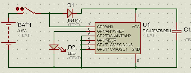
I want to know how to tell ISIS that I want the PIC in this schematic to be battery powered, I want to test some code that relies on the capacitor charge after the battery power is lost.
It's hard enough to model all the functions and firmware in a microprocessor chip without trying to model what it will do with varying levels of VCC, so I suspect the models just assume a nominal VCC voltage. What I would suggest is start by calculating worst case current consumption. Assuming U1 has a BOR, the spec sheets should give you that voltage. Estimate worst case of how long your software could take until ADC port 0 is read and then how long to execute your "shut down" routines. Now you can calculate the size of C1. If it were me, I would be inclined to increase it by a factor of 10x considering that most large caps have a +/- 20% tolerance, and most caps drop as they age. This would also be a very easy circuit to breadboard. To me, that makes more sense than trying to simulate how many instructions a microproc can execute before it browns out.
Dick Perin
Engineer
Turner Broadcasting System Inc.
Atlanta, GA, USA
I don't use an a/d on GP0, since I can just measure if its high or low, that poses no problem.
What I dont understand is how to configure ISIS to use the battery as the power source instead of the power rails defined in the template pulldown menu.
It should work with the battery. If you grab an animated LED it works fine with the battery. You might need to right click the battery to set the voltage property. FYI, you can't simulate your own PIC circuits with an evaluation version of the software. You need to purchase a license if you don't already have one.
Dick Perin
Engineer
Turner Broadcasting System Inc.
Atlanta, GA, USA